Constant Volume Dual-Duct, All-Air Systems
A dual-duct system employs a different approach for establishing zone control. In a dual-duct system, cooling and heating coils are placed in separate ducts, and the hot and cold air flow streams are mixed, as needed, for temperature control within each zone.
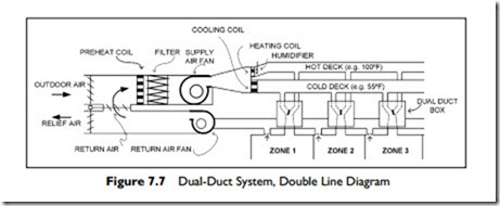
In this system, the air from the supply fan is split into two parallel ducts, downstream of the fan. One duct is for heating and the other for cooling. A layout of three zones of a dual-duct system is shown in Figure 7.7.
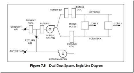
The duct with the heating coil is known as the hot deck, and the duct with the cooling coil is the cold deck. These constant volume dual-duct systems usually use a single, constant-volume supply fan to supply the two ducts.
The dual-duct system can also be drawn diagrammatically as shown in Figure 7.8. Satisfy yourself that the two figures show the same system, although they look very different.
Dual-duct systems achieve the zoned temperature control by mixing the hot and cold air streams in a dual-duct box while maintaining a constant airflow. As in the reheat system described earlier, the heating and cooling effects are fighting against each other when the load is less than peak load. The combined energy use leads to energy inefficiency, which is the biggest disadvantage of dual-duct systems. The energy inefficiency may be reduced by these methods:
Minimizing the temperature of the hot deck using control logic based on zone loads or outside temperature Raising the cold deck temperature when temperature and humidity conditions make it practical Using variable volume dual-duct mixing boxes The system also has a high first cost, since it requires two supply ducts. These two ducts need additional space above the ceiling for the second supply duct and connections.
Dual-duct systems were popular in the 1960s and 1970s and many are installed in hospitals, museums, universities, and laboratories. Due to the relatively high installation and operating costs, dual-duct systems have fallen out of favor except in hospitals and laboratories, where their ability to serve highly variable sensible-heat loads at constant airflow make them attractive. Another advantage of dual-duct systems is that there are no reheat coils near the zones, so the problems of leaking hot water coils is avoided.
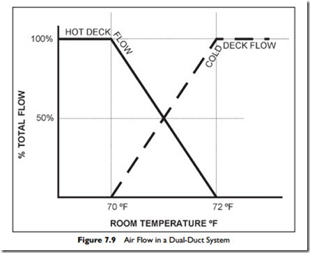
The dual-duct system delivers a constant volume of air, with varying percent- ages of hot and cold air, as shown in Figure 7.9.
In Figure 7.9, there are plots of percentage flow from the hot and cold air streams as a function of room temperature. The sum of the hot and cold air- stream percentages always adds up to 100%. For the room temperature setpoint range, also known as the throttling range, of 70°F to 72°F, the thermostat will control the hot-air flow linearly, from 100% at 70°F to 0% at 72°F. Outside the throttling-temperature range, the flow is either all hot air or all cold air.
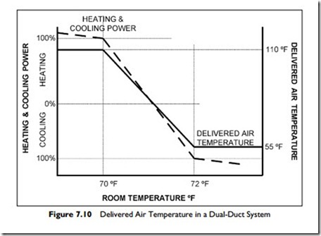
In Figure 7.10, there is a different view of the same process over the throttling range.
There are two plots. One plot, the solid line, shows how the delivered air temperature will vary as the thermostat controls the percentage mixture of hot
and cold streams. The delivered air-temperature scale is on the right-hand side of the graph, and the room-temperature scale is on the horizontal axis.
At a room temperature of 70°F and below, with 100% hot air, the delivery temperature is at 110°F. At a room temperature of 72°F and above, with 100%
cold air, the delivery temperature is 55°F. At room temperatures between 70° and 72°F, the delivery temperature varies linearly with the room temperature.
The second plot in Figure 7.10, the dashed line, is that of the net cooling or heating power delivered to the zone to meet the load. The scale for the power variable is on the vertical axis, on the left-hand side of the graph. Zero power, (or no net delivered heating or cooling) is at mid-height on the vertical axis. Above the mid-height, there is net heating and below mid-height, there is net cooling.
It is important to observe that, because this is a constant volume system, zero power does not mean zero energy use. Zero power corresponds to an equal amount of heating and cooling, so that the heating and cooling effects cancel each other out, and give a neutral temperature effect on the zone.
As shown in Figure 7.9, below a room temperature of 70°F, the flow is 100% heating at 110°F; and above a room temperature of 72°F, the flow is 100% cooling at 55°F. Between 70° and 72°F, the flow is a linear mixture of hot and cold air.
Related posts:
Incoming search terms:
- dual duct system reset schedule set up
- dual duct system
- Dual zone air duct system
- dual ducts in hvac
- Difference between dual duct and multi zone systems
- dual duct hvac system
- Dual zone duct systems are being discussed Technician A says the passenger controls only the passenger side temperature door Technician B says the driver may be in control of the rear passenger compartment temperature on some systems Who is correct?
- https://yandex ru/clck/jsredir?from=yandex ru;search;web;;&text=&etext=1832 v8l4_qSkyVFZ8TY9mJv4ow7TwN1HMdSd1CBHOvPlkAqELZfkHlSSlFXcYfCP831RMc6M8OhQ8kuP67slMI_guw 112b3ee02734089f92077c9206d52e893911500c&uuid=&state=_BLhILn4SxNIvvL0W45KSic
- hvac dual zone
- single duct system vs dual duct system
- two zone furnace system
- all air system
- dual duct system advantages
- Dual Duct HVAC Systems
- dual duct constant volume system image
- dual duct constant volume system
- dual duct constant volume
- double duct ac
- Constant volume dual duct
- when to use a duel duct air system


