Gas Furnace Components
This section contains a brief description of the principal components of a gas-fired, forced-air furnace. Additional and more detailed information about these components is found in Chapter 2, “Gas Burners”; Chapter 4, “Thermostats and Humidistats”; Chapter 5, “Oil and Gas Controls”; and Chapter 6, “Other Automatic Controls” in Volume 2. The basic furnace components are as follows:
1. Furnace controls
2. Heat exchanger
3. Gas burners
4. Gas pilot assembly
5. Blower and motor
6. Air filter(s)
Furnace Controls
Each gas furnace is equipped with a variety of different controls used to ensure its safe and efficient operation. Not every gas furnace will have all of the controls listed here. For example, a thermocouple is a safety device used in standing-pilot gas furnaces, but not in those equipped with electronic ignition systems. Check the furnace specifications and manuals for the controls used with a specific model. Detailed descriptions of these devices are cov- ered in Chapter 2, “Gas Burners”; Chapter 4, “Thermostats and Humidistats”; Chapter 5, “Gas and Oil Controls”; and Chapter 6, “Other Automatic Controls.”
Thermostat
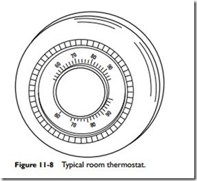
A room thermostat controls the operation of the furnace (Figure 11-8). The thermostat senses air-temperature changes in the space or spaces being heated and sends an electrical signal to open or close the automatic main gas valve. The thermostat is generally wired in series with the pilot safety valve, the automatic main gas valve, and Figure 11-8 Typical room thermostat.
the limit control. See Chapter 4 of Volume 2, “Thermostats and Humidistats” for a detailed description.
Main Gas Valve
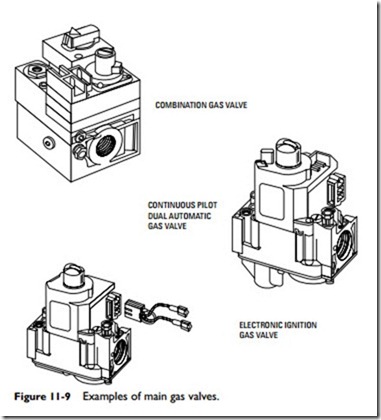
The principal function of the main gas valve is to control the flow of gas from the outside supply line (natural gas) or storage tank (propane) to the burner manifold (in the case of a burner assembly) or to the gas burner. These valves are manufactured in a variety of different shapes and sizes. They are commonly located behind the front panel of the furnace. Several different types of gas valves are illustrated in Figure 11-9. These valves are often combined with
safety shutoff devices that turn off both the main gas and the pilot gas, and/or pressure regulators that regulate the flow of gas. Such valves are commonly called combination gas valves, combination main gas valves, and intermittent-pilot dual-valve combination gas valves. The main gas valves in modern furnaces where there is no standing-pilot are sometimes called electronic ignition gas valves. The various types of gas valves are covered in greater detail in Chapter 6, “Gas and Oil Valves” of Volume 2.
Thermocouple
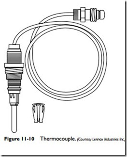
A thermocouple is a heat-sensing safety device used in a standing pilot gas furnace to determine whether the pilot is lit before the main gas valve is opened to supply gas to the burners (Figure 11-10). The heat of the pilot flame is converted by the thermocouple into an electric current. The current is strong enough to open the pilot portion of the main gas valve, which then supplies gas to the pilot light. If the thermocouple does not detect a pilot flame, it will turn off the gas supply to the pilot. The main gas valve is operated by a current from a 24-volt AC transformer. The thermocouple is described in greater detail in Chapter 5, “Gas and Oil Controls” in Volume 2.
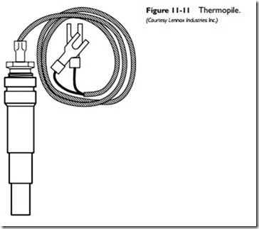
A thermopile (sometimes called a thermopile generator or a millivolt generator) is a pilot flame, heat-sensing safety device used in some standing-pilot gas furnaces instead of a thermocouple (Figure 11-11). It is larger than a thermocouple, delivers more electricity, and operates both the main gas valve and the pilot light. No transformer is required in gas furnaces equipped with a thermopile. The thermopile is described in greater detail in Chapter 5, “Gas and Oil Controls” in Volume 2.
Mercury Flame Sensor
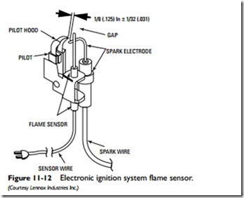
A mercury flame sensor used in an electronic ignition system is illustrated in Figure 11-12. It consists of a mercury-filled sensor end, a capillary tube, and an SPDT switch assembly on the main gas valve. The sensor end, which is filled with mercury, is directly heated by the burner flame. The mercury vaporizes and expands, forcing the remaining nonvaporized mercury in its liquid state down the capillary tube to the switch on the gas valve. The weight of the liquid mercury triggers the switch and opens the gas valve.
The mercury flame sensor is described in greater detail in Chapter 5, “Gas and Oil Controls” in Volume 2.
Gas Pressure Regulator
The gas in the supply main is frequently subjected to pressure variations. A gas pressure regulator ensures a constant gas pressure in the burner manifold. In a natural gas heating system, the pressure regulator is located in the furnace on the main gas valve. The gas pressure regulator in an LP (propane) gas heating system is located between the supply tank and the main gas valve.
Fan and Limit Control
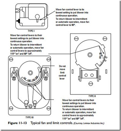
The fan and limit control is a safety device that operates on a thermostatic principle (Figure 11-13). This combined control is designed to govern the operation of the furnace within a specified temperature range (usually 80 to 150°F), and is located in the furnace plenum, where it responds to outlet air temperatures.
One of the functions of this control is to prevent the furnace from overheating by shutting off the gas supply when the plenum air temperature exceeds the upper temperature setting (180°F) on the control. The limit-control switch (and pilot safety relay) responds to excessive plenum temperatures by closing the automatic main gas valve and thereby shutting off the flow of gas to the burner or burner assembly.
Another function of the fan and limit control is to stop the fan when the gas burner or burner assembly has been turned off. When the plenum air drops below the lower setting (80°F) on the control, the fan is automatically shut off. For additional information about fan and limit controls, read the appropriate sections in Chapter 6 of Volume 2, “Other Automatic Controls.”
Related posts:
Incoming search terms:
- standing pilot gas furnace components
- A __________is used in standing-pilot light gas furnaces to determine whether the pilot flame is lit before the main gas valve is opened to supply gas to the burners
- Mercury flame sensors
- safety devices for gas furnaces
- used in standing-pilot light gas furnaces to determine whether the pilot flame is lit before the main gas valve is opened
- what safety device in furnace open gas valve
